
Francisco Javier Cruces Doval
Friday, September 8, 2023 | 11 minutes
GNS3 switch configuration
You will learn to configure switches in GNS3, both generic devices and Cisco switches, using the VLans concept to segment the network and explore the complexities of network management.
Stage preparation
The first thing I’ll do is set up the stage:
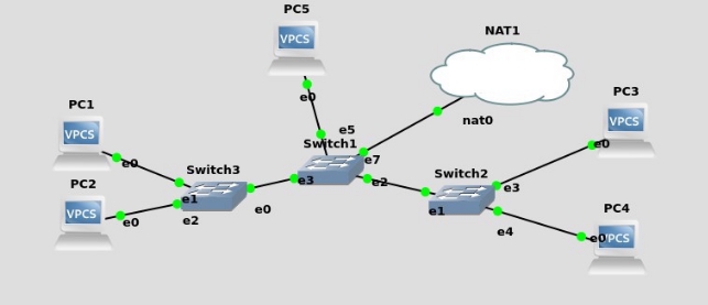
Customer network configuration
Then set up the network cards of the customers, taking advantage that the NAT cloud includes a DHCP server.
To do this, we write on the VPCS the following command:


Exercise A
1 PC1 and PC3 belong to VLAN 10, PC2 and PC4 belong to VLAN 20. It shows the correct functioning of both VLAN and that there is no connectivity between PC2 and PC3. Can you do it with the Ethernet switches that GNS3 brings? You find any limitations? What are the different types (types) that a port can have and where do they differ?
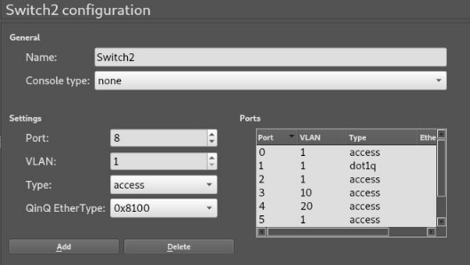
To configure the VLANS in the switches, we right-click and then we make the following configuration:
For switch 3 (PC1 and PC2)

For switch 2 (PC3 and PC4)
For switch (PC5 and NAT1)

PC1, you will only have connectivity with the PCs that belong to your VLAN:

PC2, you will only have connectivity with the PCs that belong to your VLAN:

With their respective partners from the other switch we will get the same result. PC3, you will only have connectivity with the PCs that belong to your VLAN:

PC4, you will only have connectivity with the PCs that belong to your VLAN:

We have to keep in mind that devices that do not belong to the VLAN 10 must be manually configured as they do not have connectivity to the DHCP server.
Exercise A can do it perfectly with the switches that GNS3 brings, we will find an important limitation, as the switches only allow the mouths to belong to a VLAN.
In performing the exercise we must take into account the types that a port can have, the ones we have used are the first two:
- Access: This is the one for a final team, that is a customer, as it is responsible for removing the labelling that goes on the header.
- Dot1q: This is in charge of interconnecting network devices with each other, is in charge of adding the labelling in the header to send the package to another device and let it know to which VLAN belongs.
- QinQ: It is similar to dot1q but it is also in charge of adding the type of package to the label to identify them.
With this in mind we can do an analogy with the practice of physical switches: The untagged ports –> Access
The ports tagged –> Dot1q
By using these switches protocol 802.1Q but “with less functions” we cannot indicate that VLANS we want you to use the ports configured as Dot1q, but that through the VLAN by default pass the labelled packages of all VLANS.
Exercise B
2 All computers must be able to access the data server, but only PC1 and PC3 must access the Internet. They will do it through your physical machine using the element called NAT, which you will need to understand and configure. Can you do it with the Ethernet switches that GNS3 brings? What limitation do you find? To overcome this limitation, download the CISCO 3725 as application and use it instead of the Ethernet switches by setting them up properly.
Switches Ethernet
Here we find the first limitation of these switches, as we can only have 1 VLAN per port this means that only a VLAN will have access to these resources.
As we want only VLAN 10 to browse the Internet we will set the mouth of our cloud to a mouth with access type and belong to this VLAN:

So for this point there is no problem, our PC1 and PC3 will both be able to browse the Internet:

As these 2 PCS belong to the same VLAN that the NAT cloud can communicate smoothly and use the DHCP server that includes the same to configure. While PC2 and PC4 cannot navigate or be configured by DHCP by not belonging to the same VLAN as the NAT cloud:

With the data server we will run into the limitation as only a port can belong to a VLAN, only a couple of our PCs can communicate. This could be avoided by setting up the server as a “real machine” with 2 virtual interfaces and telling the switch that each one belongs to a different VLAN.
CISCO 3725
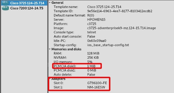
To start using this device, we will have to add space to the disk so that we can start it, and we can add the 16-mouth Ethernet module by default so we won’t have to do it by hand later.
To make this configuration we must have imported the router and access Edit > preferences > IOS routers.
Once the template is modified, we will place the 3725 on the stage and set up the same scenario:

We must bear in mind that the FastEthernet0/0 and FastEthernet0/1 interfaces work as routers, that is, we cannot use them as switch. The ports that behave as a switch are all of FastEthernet1 so it will be the ones we use.

We will then tell these ports that they have to work as if they were a switch for it we will introduce the following commands in each of the 3725.


We will now create the vlans using the following commands, for each of the switches:

We can list them with the following command:
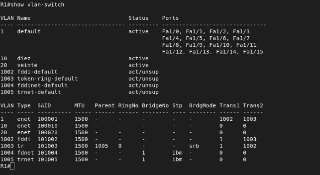
We will now assign your corresponding VLAN to the ports:


Then we will configure the port that unites the two 3725, for this we put it in trunk mode and allow the encapsulated traffic of all the VLANS through this port.

Finally, we will save the changes so that if the equipment is turned off, it will maintain the modifications we have made:

With this we will have configured the first 3725, its homologue to this, that is to say the one that connects to PC3 and PC4, we would have to do the same adapted to the ports in which the devices are connected.
We will continue to configure the 3725 that unites both “switches” and gives output to the data server and the Internet. For this we will create VLANS 10 and 20:

And we will assign both VLANs to the data server, while only VLAN 10 will be assigned to the internet connection.


We will now set up the interfaces that interconnect the switches:

Then we will create the two subintrants to allow traffic between them and we will assign you ip addresses.

Now the data server will connect it to the Fe0/0 port and in it will create two subintrants, I will use a debian machine. This will be done by editing it on network interfaces:

We check that the interfaces are up:

We will now create the routing routes:

Once this is done, we can do ping to the data server from the two interfaces:

We can ping the data server and we will have connectivity with the:

We see that the traffic is able to reach the data server however it is not able to “make the way back.”
I have also set up inter vlan routing, following the links of the literature but it has not worked for me either.
Exercise C
It answers the following questions on the above paragraphs:
C.1 What about the direction when you add the NAT cloud? What is the reason for this change?
When we put the NAT cloud, it includes a DHCP server which has the address ip 192.168.122.1 and assigns addresses to the network 192.168.122.1/24. Through the configuration provided by this will allow us to browse the Internet.
C.2 Why is it necessary to assign a hard drive to each of the devices and what minimum size should it have for the scenario to work?
For the 3725 cisco routers, for it to start and exceed the initial check it must have at least 1MB space, and if we want to save the settings this will be necessary. For example to save the information of the vlans it will be necessary.
**C.3 What is the difference between setting up a switch port in mode **access **and mode **trunk and when each of them should be used?
The access mode is designed to connect a final client that is, a pc. It is the equivalent of the “untagged port,” however this has a limitation which is that it can only belong to a van, this port is also in charge of removing the header that the trunk ports add so that the final devices can understand the packages.
On the other hand, the trunk mode allows to connect a network device to another, for example a switch to another switch, would be the equivalent of a “tagged port,” this also allows the traffic of several vlans, tagging the tracks so that the other devices can interpret the VLAN to which the package belongs.
Exercise D
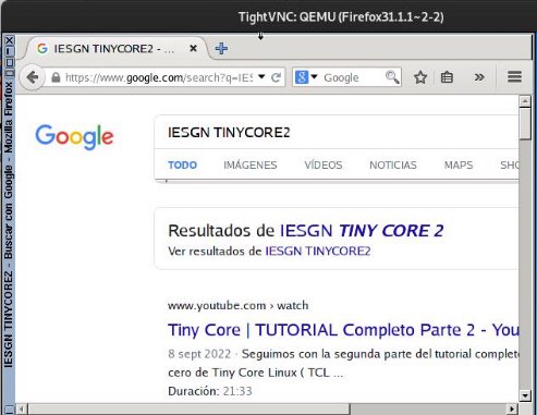
**Now replace PC1 and PC3 with two machines **Linux with Firefox installed (you can find the images in the GNSS Market Place) and check that they navigate correctly.
We added it to the stage and connected them to the same mouths that our VPCS had to maintain the previous configuration of the VLANS and have access to the NAT cloud.

Once this is done, we will access the machine interface and configure your network card by DHCP, so we will access the control panel:

In the control panel we access network to configure the network:

In the network panel we will say to use DHCP and save the configuration:

In the terminal we can make sure that the network configuration has been performed correctly.

And we can see that by doing this procedure we can already navigate with the tinycore with Firefox:

Here’s the test with the second tiny core:
Exercise E
Set up a Port Bonding between the header switch and the other two. It shows its proper functioning and explains in detail how you set it up. Explain the lags that a carrier can have.
Then we must set up the extra ports we have added to the stage to be in trunk mode and respect our scenario with the VLANS, is to repeat what we have done before.
The first thing we will have to do will be to create the logical interfaces, however this step can be omitted as later if the interface does not exist it will automatically create it.

We will indicate that interfaces we want them to belong to the port-channel 1 for the logical link between R1-R2 and to belong to the port-channel 2 for the logical link between R2-R3.
For R1-R2:

For R2-R1:

For R2-R3:

For R3-R2:

We can also configure the EtherChannel as a trunk link, and so we get statistical multiplexation of the traffic of the VLANs and that when one link falls it still works with both VLANs. We will do this with all the logical links:

Once this is done we can check if the etherchannels are working:


The EtherChannel configuration can be done using one of these protocols: Port Aggregation Protocol (PagP) or Link Aggregation Control Protocol (LACP). Both ends must be configured in the same way.
These have a series of “modes” in which the behaviour of the port will change when creating links:
- on: In this mode, group member links will be added manually and not automatically monitored. This mode is used when you want to have greater control over group member links.
- desirable: In this way, the switch will try to negotiate with the connected device at the other end of the link. If the other end device is also configured in “desirable” mode, the link will be automatically added.
- car: In this mode, the switch will not attempt to negotiate but will automatically add the link if the connected device at the other end of the link is configured in “desirable” mode.
- active: In this mode, the switch will constantly send LACP PDUs to determine whether the connected device at the other end of the link is available and also configured to use LACP. If the other end device is available and also configured to use LACP, the link will be automatically added.
Exercise F
Port Mirroring: Connects a PC5 to Switch1 and monitors the traffic leaving PC1. It makes a Wireshark capture in the PC5 mouth and explains the traffic captured.
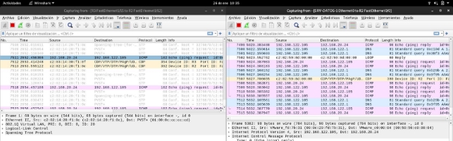
The first thing we will do is set up the port mirroring, in my case will send the traffic from the 1 / 5 mouth to the 1 / 4.

I will make the pc5 a ping to google and monitor the cable that goes from the router to pc4, to check that the port mirroring is working:

We see that we have been able to “intercept” a ping, coming from the ip6 address.

This will make the incoming and outgoing traffic from the port we have put as a sniffer send it back to the port we hear.
We can check the status of the port viewing session with this command:

Bibliography
- Switching and GNS3
- The NAT node
- Simulando switch cisco en GNS3
- GNS3, adding hosts to our topologies
- Working with switch in GNS3: VLAN and Trunk
- LACP and PAGP
- InterVLAN routing
- VLAN routing
- Configure Port Bonding
- Link Aggregation Control Protocol (LACP) and Port Aggregation Protocol (PAGP)
- Wiki EtherChannel
- Inter VLAN Communication